Wednesday, May 14, 2025
Friday, November 03, 2023
Teardown of Cheap Digital Protractors
I recently bought a "Digital Protractor", as I was curious about how it works. On Amazon, the price was about 16 USD.
So here is a visual teardown, in 4 easy photos. :-)
I was hoping there would be a hidden data port, similar to what is found on Digital Calipers, but no such luck. The basic mechanism its similar: as circular track instead of a linear track.
Tuesday, September 19, 2023
Fixing a Corroded Battery-Bay Module on HP-41CV Calculator
Tools and Materials Needed
- Fine-pointed soldering iron
- Flux solder paste and application brush
- Brass shim stock (0.001")
- Scissors for cutting shim stock
- X-acto or scalpel knife
- Bristle brush
- Tweezers
- Isopropyl Alcohol (IPA)
- Super-glue
Method Procedure
Wednesday, May 04, 2016
TrackR-Eddystone -- it's alive!
I have put all the pieces back together and now have on-person Eddystone device! I'm just a walking beacon! :-)
I have created a short video, which is pretty terse, but give a basic demo the TrackR-Eddystone device beaconing the URL to this blog. This is heard by my iPhone which has the Chrome Physical Web extension (see prior post for details).
Friday, April 29, 2016
How to open the TrackR device
Thursday, March 17, 2016
Eddystone beacon firmware on TrackR hardware
The basic operation is fairly simple. For the first 20 seconds after battery-insertion the TrackR device advertises in connect mode. During this time the blue LED will slowly flash. This allows the user the option to change the beaconing URL If no connection is made and the 20 seconds timeout happens, the TrackR enters true Eddystone beaconing mode. Only by power-cycling (battery removal/insertion) will the device enter update mode again. I have set the default URL to Google's Eddystone documentation, but again, the URL can be changed.
The utility I recommend for changing the URL is Nordic's Master Control Panel (MCP). This Android app allows you to connect to a Bluetooth Low-Energy device. Once you establish a connection, the blue LED will true solid. Below is a screenshot showing the Eddystone Service and Characteristics. Clicking on the up-arrow icon on the right side of the URL characteristic, a pop-up dialog will allow you to enter a new URL. Select "Text" type and then enter the shortened URL string. This string must be 17 characters or less. The recommended way to shorten the URL is through an online URL Shortener utility, such as Google's or others.
Once you disconnect from device, there will be a 20 second timeout, after which the TrackR will enter Eddystone mode and begin beaconing the new URL.
You can use Google's Physical Web app, available in PlayStore, to listen for Eddystone devices. This app is also available in the PlayStore.
Below is a screenshot showing the Physical Web app recognizing my TrackR + Eddystone beacon in tabular form.
Below is another useful Android app: the Eddystone Validator. Again, it's in the PlayStore. This app will show all three info items beaconed by Eddystone: UID, URL, and TLM. The TLM info contains the TrackR's temperature, which should be close to the ambient temperature: 18.0C in this case. The battery voltage is also available, in millivolts: 2892mV in this case.
While developing the firmware, I really wanted the ability to display debug output via a serial interface. The nRF51822 has two UARTs, but the TrackR doesn't have any connection points specifically for console support.
My solution was to repurpose the two buzzer lines and use them for the UART's TX and RX lines.
An overview of this is shown below. The USB-to-Serial-ttl module is a FTDI FT232RL based designs, sold through SparkFun.
Friday, March 04, 2016
Establishing a SWD Connection to the TrackR
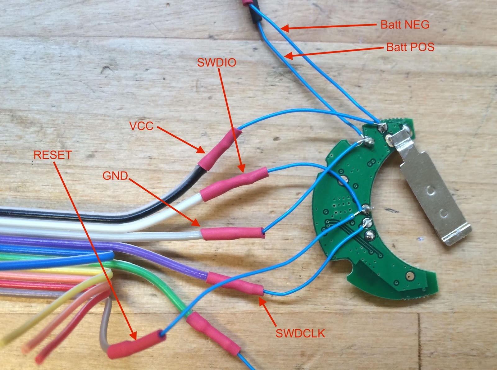
TrackR to SWD Adapter Connection Overview |
knots:~ robin$ JLinkExe -if SWD -device nrf51822_xxab -speed 1000
SEGGER J-Link Commander V5.10f (Compiled Dec 22 2015 14:25:20)
DLL version V5.10f, compiled Dec 22 2015 14:25:14
Connecting to J-Link via USB...O.K.
Firmware: J-Link ARM Lite V8 compiled Oct 29 2014 09:03:16
Hardware version: V8.00
S/N: xxxxxxxxx
License(s): GDB
Emulator has Trace capability
VTref = 2.957V
Type "connect" to establish a target connection, '?' for help
J-Link>connect
Device "NRF51822_XXAB" selected.
Found SWD-DP with ID 0x0BB11477
Found Cortex-M0 r0p0, Little endian.
FPUnit: 4 code (BP) slots and 0 literal slots
CoreSight components:
ROMTbl 0 @ F0000000
ROMTbl 0 [0]: F00FF000, CID: B105100D, PID: 000BB471 ROM Table
ROMTbl 1 @ E00FF000
ROMTbl 1 [0]: FFF0F000, CID: B105E00D, PID: 000BB008 SCS
ROMTbl 1 [1]: FFF02000, CID: B105E00D, PID: 000BB00A DWT
ROMTbl 1 [2]: FFF03000, CID: B105E00D, PID: 000BB00B FPB
ROMTbl 0 [1]: 00002000, CID: B105900D, PID: 000BB9A3 ???
Cortex-M0 identified.
J-Link>h
PC = 000119CE, CycleCnt = 00000000
R0 = 20000103, R1 = 00000032, R2 = E000E200, R3 = 00000032
R4 = 00000000, R5 = 20002AB4, R6 = 00000000, R7 = 00000000
R8 = FFFFFFFF, R9 = FFFFFFFF, R10= 0001CFF0, R11= 0001CFF0
R12= FFFFFFFF
SP(R13)= 20003AF0, MSP= 20003AF0, PSP= FFFFFFFC, R14(LR) = 0000116B
XPSR = 61000000: APSR = nZCvq, EPSR = 01000000, IPSR = 000 (NoException)
CFBP = 00000000, CONTROL = 00, FAULTMASK = 00, BASEPRI = 00, PRIMASK = 00
J-Link>s
000119CE: 40 BF SEV
J-Link>s
000119D0: 20 BF WFE
J-Link>s
000119D2: 41 78 LDRB R1, [R0, #+0x01]
J-Link>s
000119D4: 03 78 LDRB R3, [R0]
J-Link>s
000119D6: 43 70 STRB R3, [R0, #+0x01]
Thursday, March 03, 2016
A Tear-down of TrackR Device, a Bluetooth-Low-Energy Based Locator Fob
Yesterday I noticed it again on my dresser and began wondering what Bluetooth Low-Energy chipset was being used in it...you can already tell this isn't going to end well for the TrackR device.
Anyway, one thing lead to another and I am now pushing out a simple tear-down of the TrackR device.
![]() |
The TrackR Locator Fob |
Above is a photo of the intact TrackR device. It's really quite small and thin. There are apps for both Android and iOS.
To open the shell case, use an X-acto knife and gently slide the blade between the aluminum shell and the middle black plastic casing. The shell adheres to the casing with double-sided tape, and should be relatively easy to open. A little prying is needed, but be careful as the aluminum shell is soft and easily deformed if you're not careful.
Once you have completely remove the middle black casing, you can clean the sticky tape from the shell with alcohol or the like. Again, be gentle with the shell as it can be bent easily and the hinge can suffer from metal fatigue easily.
![]() |
Major Parts of the TrackR |
Above shows the major components after the shell has been removed. It is a surprisingly nice design/layout for such a relatively inexpensive device.
![]() |
Close-Up of TrackR Internals |
Above is a close up of the casing with the PCB board inserted.
![]() |
Annotated TrackR PCB Board (Front Side) |
The above annotated photo shows many of the interesting features for the TrackR PCB board. I was pleasently surprised to see that the nRF512822 (QFABC0) was used. This is the smallest (memory-wise) chip in the nRF51822 series, with 128K of flash, 16K RAM, and an ARM Cortex-M0 processor.
![]() |
Annotated TrackR PCB Board (Back Side with Pogo Pin Pads) |
The above photo shows the back side of the TrackR PCB board. Notice the several circular metallic dots (pads) exposed. There are probably pogo-pin pads used during manufacturing.
The SWDxxx pads are ICP (In Circuit Programming), e.g. loading the firmware onto the device.
The other pads are probably for QA testing during manufacturing to insure the boards works properly. This allows the components which are more likely to fail during the manufacturing process to be tested: Buttons and buzzer are items which often are faulty.
![]() |
TrackR Aluminum Shell Case (Note Non-Anodized Area for Antenna Contact) |
The above photo shows the aluminum shell's inside. The most significant feature is the non-anodized (silvery) area. This is where the antenna connector (spring-finger) contacts the shell. In other words, the shell is acting as the antenna.
Later, given some time, I might attempt to reprogram the TrackR with, say, Eddystone firmware. This will allow the TrackR device to participate in the Google's "Physical Web" initiative. There are apps for Android and iOS which interact with Eddystone devices. I suggest reading about Eddystone and the Physical Web, if you're interested. My github site has a project for Eddystone firmware of the Nordic PCA1001 board, which should be a good starting point for porting to the TrackR board.
Wednesday, January 27, 2016
Easy DFU Operation: Activating the nRF Toolbox DFU applet from your Android app.
The general outline is that I write a test app which is used by me (nRF51 firmware developer) to exercise the firmware. This test app is also used by other (mobile-side) developers to update the firmware on their devices.
So the general interaction is to start the Test app (seen below) and after connected, hit the "DFU" button. This will send the DFU-activation sequence to the selected device over BLE. Upon completion of this sequence, the device should be in DFU mode (e.g. executing in the bootloader) and advertising itself as "DfuTarg".
The final Test app step is to invoke the standard Nordic "nRF Toolbox" app, which will immediately display the nRF Toolbox's "DFU" applet. This is accomplished by the Test app creating an "intent" which targets the nRF Toolbox app: it starts the nRF Toolbox app's DFU applet and immediately displays the DFU screen. From that point the user can select the update file (*.zip) and the target device, per normal for this DFU applet.
NOTE: This code snippet is rather crude and could be improved greatly, but the general flow outline should give you a general operational idea. This was tested on Android Lollipop with a Nexus 7 tablet. YMMV on other versions or hardware.
private static final String DFU_PACKAGE = "no.nordicsemi.android.nrftoolbox/no.nordicsemi.android.nrftoolbox.dfu.DfuActivity"; private void triggerDFU() { Thread thread = new Thread() { @Override public void run() { try { Log.d(TAG, String.format("enable Indicates for ServiceChanged")); mBleWrapper.setIndicationForCharacteristic(mServiceChangedCharacteristic, true); sleep(1000); Log.d(TAG, String.format("enable Notifys for DfuControlPoint")); mBleWrapper.setNotificationForCharacteristic(mDfuControlPointCharacteristic, true); sleep(1000); Log.d(TAG, String.format("write DFU-Start to DfuControlPoint")); byte[] dfuStart_bytes = new byte[12]; dfuStart_bytes[0] = 0x01; // Start DFU dfuStart_bytes[1] = 0x04; // Application mBleWrapper.writeDataToCharacteristic(mDfuControlPointCharacteristic, dfuStart_bytes); dfuDelayHandler.postDelayed(new Runnable() { @Override public void run() { try { Intent intent = new Intent(Intent.ACTION_MAIN); intent.setComponent(ComponentName.unflattenFromString(DFU_PACKAGE)); intent.addCategory(Intent.CATEGORY_LAUNCHER); intent.setFlags(Intent.FLAG_ACTIVITY_NEW_TASK); PeripheralActivity.this.startActivity(intent); } catch (Exception e) Toast.makeText(PeripheralActivity.this, "The \"nRF Toolbox\" app was not found. Please install it.", Toast.LENGTH_LONG).show(); } finish(); } }, DFU_DELAY); } catch (InterruptedException e) { e.printStackTrace(); } } }; thread.start(); }
Tuesday, December 01, 2015
Working with Eddystone -- Bluetooth Low-Energy Beacon
I have a Eddystone github project which I am able to experiment and play with this type of beacon.
The cool thing is that Google has provided several mobile-side apps which allow firmware developers to works with non-trivial apps.
On the Android there is an app, "Physical Web" which scans and lists any Eddystone beacons in the area.
On the iOS side, Google's Chrome browser has extended into the "Today" applet to list PhysicalWeb devices which include Eddystone.
Wednesday, January 14, 2015
Nordic nRF51822 PCA10001 Support for Pervasive Display Extension Board and 1.44" ePaper Display
Nordic's nRF41822 Evaluation Kit contains the PCA10001 board which has the nRF51822 SoC and support circuitry useful for prototyping.
Below is a photo of the setup, showing the cabling between the two boards.
Details can be found at the github project.
The basic system is built upon and extends the Nordic nRF51 SDK example code for a virtual UART device over Bluetooth Low-Energy (BLE): the extension being support for the e-Paper display.
A phone or tablet with the Nordic-supplied nRF-UART app installed (Android version or iOS version) is used to communicate with the ble_app_epd firmware running on the PCA10001 device.
Basically this virtual UART provides a simple terminal emulation onto the PCA10001.
From this terminal emulation, the user can type the "show" or "clear" commands to invoke the e-Paper actions.
This project is a relatively simple "starter" application for Pervasive Display e-Paper support on the nRF51822 SOC. But is should provide the basic support needed for more ambitious e-Paper projects.
NOTE: This nRF51822 Evaluation Kit is being phased-out, but the new Eval Kit should work as well. At this time, the original kits are still available in many of the standard supply chains.
Saturday, July 19, 2014
Starbucks location 1
Starbucks location 2
Starbucks location 3
While the audio is generally weak, if you turn up the volume, the reactions from the baristas were quite remarkable. After the purchase, several of the customers, off camera, would ask how they could do that too. My wife and I were a bit overwhelmed by the positive comments. Interestingly, as we make the rounds, I was becoming concerned that my loyalty card would run out of credits, but fortunately, that didn't happen. :-)
Wednesday, July 16, 2014
The shape of the Pebble's display, which is nearly square, seemed best suited for QR barcodes. After about couple of weeks playing around, I finally stitched together a Pebble watch app and an complementary Android app, called "QR_Safe". I can now create QR codes on the Android side and send them to the Pebble watch to be saved in its flash memory. I currently support four slots, where each slot has a custom title to identify the QR code content.
Today was my big test for all this: I encoded my Starbuck's loyalty card number as a QR barcode and saved it to my Pebble. At my local Starbucks I was able to pay for my beverage with the QR barcode displayed on my Pebble...it all worked!
Tuesday, June 10, 2014
Recently, I have been playing with a Pebble SmartWatch interacting with an Android tablet, a Google Nexus-7. In particular, I have built a pair of apps, one on the watch side which sends accelerometer data to the other on Android side, where the components of the accelerometer vector are shown as X, Y, and Z axis on real-time strip-chart (plot). These paired apps form a distributive system, which in itself is not too terribly useful. The point exercise is to enable some foundational infrastructure upon which I can build more interesting apps.
The complete source code for this project, called PebblePointer, can be found at https://github.com/foldedtoad/PebblePointer. Take a look at the README.md file and the wiki page for details.
A demo youtube video of this can been found at https://www.youtube.com/watch?v=7Hh2fFXfahk
Here is a screenshot from the Android side.
Tuesday, March 23, 2010
Linksys WRT54G with bluetooth console access
So I have found two solutions which don't require modifying the case.
The first is too simple to go into detail, but I just route the ribbon cable through the top two section of the router case. This leaves a small, unaesthetic gap where the ribbon cable pushes though and for this reason I am have move to the second solution.
My prefered solution for general router console access is via a Bluetooth connection. This Bluetooth connectivity is provided with a Bluetooth module such as the "BlueSMiRF" module sold by SparkFun (see note below). The Bluetooth connection is based on the SPP/RFCOMM profiles which this module supports. Access from Windows, Macs, and Linux systems quite easy. I use hyperterm on Windows-based systems and minicom on Linux-based systems.
A description of my procedures --
I constructed a new header cable with the standard 5x2 header and 10 strand ribbon cable. The cable length should be about one foot long (30cm) or so. The UART pins on the router board header are layed-out such that odd-numbered pins are UART0 and even-number pins are UART1. You can see in the photo below how, on the cable, I split-out the individual strands for each uart. I used shrink-tubing to re-gather the strands. I then soldered 4pin headers onto the ends of each cable branch. Be sure to cross-over the TX and RX cables at this time. Notice that the UART pins 4 and 8 are not connected and I just tucked them back into the shrink-tubing.
The new dual-headed cable should now be ready for use.
I connected an old "BlueSMiRF" module I bought from SparkFun years ago. The pin layout matched the layout of the new cable header. Then I "paired" the PC with the BlueSMiRF module and opened hyperterm using the new virtual com port. Tap a couple of [enter] and a prompt from the linksys shell should appear.
At this point I normally would stick the bluetooth module to the inside roof of the linksys case with double-side foam tape, and tuck the cable into the case before closing it. When closed up, the case should show no signs of this modification.
Since I didn't have two Bluetooth modules, I used a Serial-to-USB adapter with a RS-232-to-TTLv3 level converter to interact with the second UART. The last image shows a simple test in which the console UART sends a short message to the second UART.
Notes:
1) Be sure to consider how to handle RTS/CTS on your bluetooth module. For the "BlueSMiRF" there is a 0-ohm pads which will short CTS to RTS. Your module probably has a similar option.
2) The second UART on the header usually is initialized at 9600 baud, not 115200 baud.
3) I don't believe SparkFun offers the same BlueSMiRF module as I used. The replacement part appears to be the "BlueSMiRF Gold", which is based on the Roving Networks module. This substitution should work without problems.
Friday, January 15, 2010
The FLEX Project
Monday, October 19, 2009
Android Emulator (Goldfish) Big-Screen Support
In a perfect world, these hacked-in changes should be folded into the kernel configuration, e.g. Kconfig files, to allow ease in selecting and understanding. For example, the CONFIG_FORCE_MAX_ZONEORDER should be the perfered setter for MAX_ZONE, but Goldfish does not select this option.
As can be imagined, these changes have an impact on performance and so you'll want to run the emulator on a hefty system: 3Ghz processor, 2GB memory, and of course a good graphics adapter.
Below is a simple patch for these changes.
index bf7c737..58127bc 100644
--- a/arch/arm/include/asm/memory.h
+++ b/arch/arm/include/asm/memory.h
@@ -114,7 +114,7 @@
* between 2MB and 14MB inclusive.
*/
#ifndef CONSISTENT_DMA_SIZE
-#define CONSISTENT_DMA_SIZE SZ_2M
+#define CONSISTENT_DMA_SIZE SZ_8M // android big-screens
#endif
/*
diff --git a/include/linux/mmzone.h b/include/linux/mmzone.h
index 428328a..9e92b16 100644
--- a/include/linux/mmzone.h
+++ b/include/linux/mmzone.h
@@ -21,7 +21,7 @@
/* Free memory management - zoned buddy allocator. */
#ifndef CONFIG_FORCE_MAX_ZONEORDER
-#define MAX_ORDER 11
+#define MAX_ORDER 12 // android big-screen
#else
#define MAX_ORDER CONFIG_FORCE_MAX_ZONEORDER
#endif
Monday, August 31, 2009
Saturday, August 01, 2009
Varia's Rumble-Mini
Here are some photos of Vairia's project, codename "Rumble-Mini" which I work on. This photo shows the Rumble-Mini device (based on Freescales i.MX-37 SoC). It runs the same application as the Varia Ibiza, which allows wifi-access to RealNetwork's Rhapody. The Rumble-Touch has a capacitive touchpad (not an overlay to LCD like the Rumble-Touch), 8 Gbytes of memory, and a WiFi radio. The operating system is Linux 2.6.24. The target price is in the $99 range.
Working on Rumble-Touch's touchscreen
This photo was taken when I was working on the touchscreen for Rumble-Touch. I wrote the Linux touchscreen input driver which controls the Analog Devices AD7147 capacitive-senor device.
When all these splayed-out parts are stuffed in the case, the LCD panel folds under the touchscreen glass and the battery is next to the main PCB. It all fits together into quite a small package.
Rumble-Touch side-by-side with iPhone
See http://en.wikipedia.org/wiki/Touchscreen#Capacitive for an overview of this technology.
Varia's Rumble-Touch
Here are some photos of Vairia's project, codename "Rumble-Touch" which I work on. These photos show the Rumble-Touch hardware (based on Freescales i.MX-37 SoC) running Android. It can also run the same application as the Varia Ibiza, which allows wifi-access to RealNetwork's Rhapody. The Rumble-Touch has a capacitive touchscreen, 8 or 16 Gbytes of memory, WiFi and Bluetooth radios. The operating system is Linux 2.6.24. The target price is in the $150 range.
Saturday, May 16, 2009
Our apartment building in Tokyo
The other day, I was curious as to whether Google Maps had a street-view of our old digs. It took some doing (Tokyo streets are quite difficult to navigate), but I was able to find the place.
Still looks pretty much as when we lived there. Our apartment was on the lower left side of the building on the ground floor.
Monday, June 20, 2005
Thursday, June 16, 2005
Thursday, June 02, 2005
Sunday, May 29, 2005

I recently visited my sister, who lives near Brisbane Australia, for about three weeks. While I was there I was able to capture several weather satellite images from their "hinterland" home site. As the equipment was all hand-held radios/antennas/etc. the images a not the best. But it was fun anyway! Notice the yellow + for the approximate location of where this image was taken.