Eddystone beacon firmware on TrackR hardware
So I was able to write new firmware for the TrackR and program it into the TrackR's flash memory. This new firmware implements Google's "Eddystone" beacon. The firmware is available on my github project.
The basic operation is fairly simple. For the first 20 seconds after battery-insertion the TrackR device advertises in connect mode. During this time the blue LED will slowly flash. This allows the user the option to change the beaconing URL If no connection is made and the 20 seconds timeout happens, the TrackR enters true Eddystone beaconing mode. Only by power-cycling (battery removal/insertion) will the device enter update mode again. I have set the default URL to Google's Eddystone documentation, but again, the URL can be changed.
The utility I recommend for changing the URL is Nordic's Master Control Panel (MCP). This Android app allows you to connect to a Bluetooth Low-Energy device. Once you establish a connection, the blue LED will true solid. Below is a screenshot showing the Eddystone Service and Characteristics. Clicking on the up-arrow icon on the right side of the URL characteristic, a pop-up dialog will allow you to enter a new URL. Select "Text" type and then enter the shortened URL string. This string must be 17 characters or less. The recommended way to shorten the URL is through an online URL Shortener utility, such as Google's or others.
Once you disconnect from device, there will be a 20 second timeout, after which the TrackR will enter Eddystone mode and begin beaconing the new URL.

You can use Google's Physical Web app, available in PlayStore, to listen for Eddystone devices. This app is also available in the PlayStore.
Below is a screenshot showing the Physical Web app recognizing my TrackR + Eddystone beacon in tabular form.

Below is another useful Android app: the Eddystone Validator. Again, it's in the PlayStore. This app will show all three info items beaconed by Eddystone: UID, URL, and TLM. The TLM info contains the TrackR's temperature, which should be close to the ambient temperature: 18.0C in this case. The battery voltage is also available, in millivolts: 2892mV in this case.

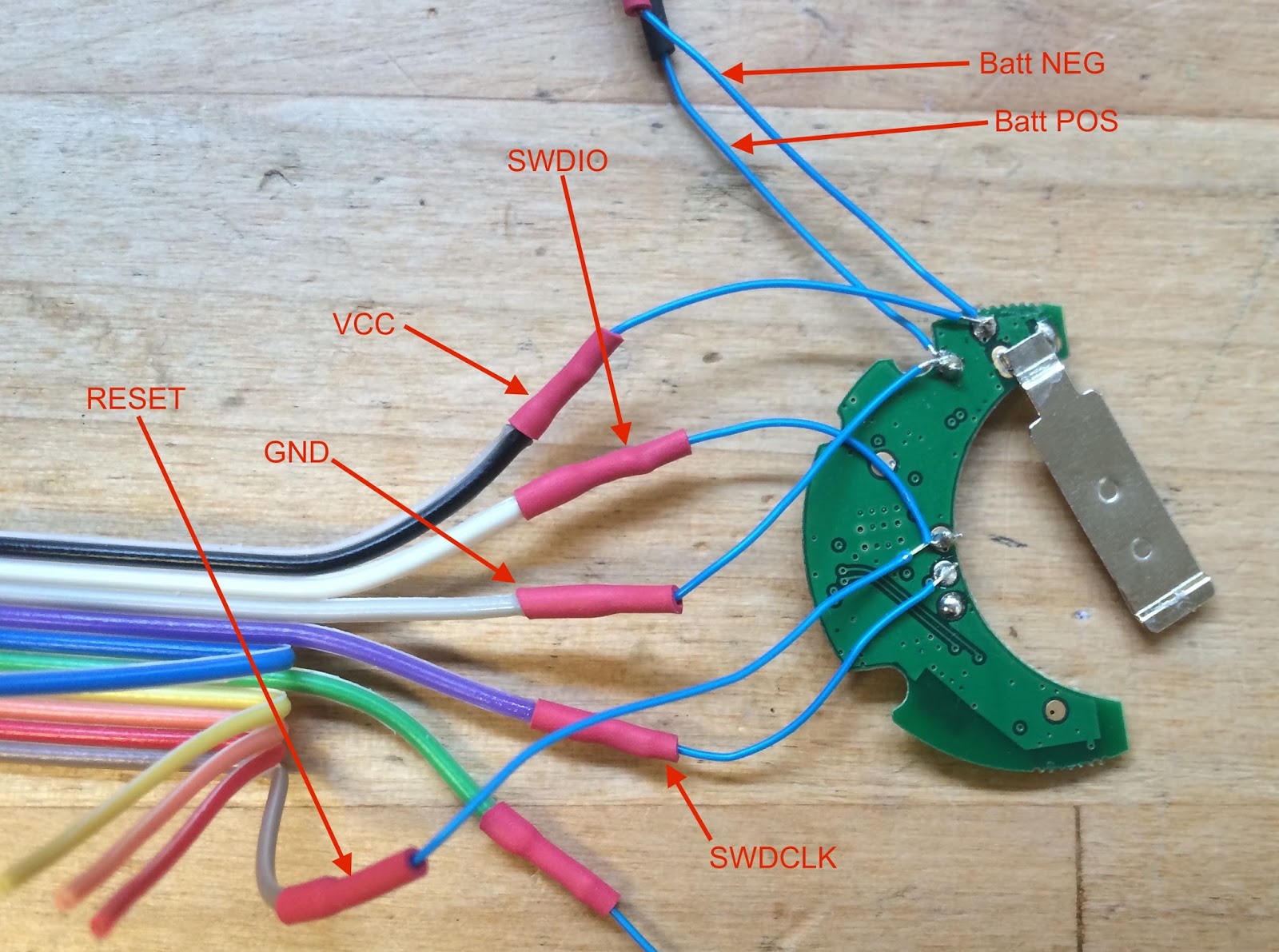
While developing the firmware, I really wanted the ability to display debug output via a serial interface. The nRF51822 has two UARTs, but the TrackR doesn't have any connection points specifically for console support.
My solution was to repurpose the two buzzer lines and use them for the UART's TX and RX lines.
An overview of this is shown below. The USB-to-Serial-ttl module is a FTDI FT232RL based designs, sold through SparkFun.

The basic operation is fairly simple. For the first 20 seconds after battery-insertion the TrackR device advertises in connect mode. During this time the blue LED will slowly flash. This allows the user the option to change the beaconing URL If no connection is made and the 20 seconds timeout happens, the TrackR enters true Eddystone beaconing mode. Only by power-cycling (battery removal/insertion) will the device enter update mode again. I have set the default URL to Google's Eddystone documentation, but again, the URL can be changed.
The utility I recommend for changing the URL is Nordic's Master Control Panel (MCP). This Android app allows you to connect to a Bluetooth Low-Energy device. Once you establish a connection, the blue LED will true solid. Below is a screenshot showing the Eddystone Service and Characteristics. Clicking on the up-arrow icon on the right side of the URL characteristic, a pop-up dialog will allow you to enter a new URL. Select "Text" type and then enter the shortened URL string. This string must be 17 characters or less. The recommended way to shorten the URL is through an online URL Shortener utility, such as Google's or others.
Once you disconnect from device, there will be a 20 second timeout, after which the TrackR will enter Eddystone mode and begin beaconing the new URL.

You can use Google's Physical Web app, available in PlayStore, to listen for Eddystone devices. This app is also available in the PlayStore.
Below is a screenshot showing the Physical Web app recognizing my TrackR + Eddystone beacon in tabular form.

Below is another useful Android app: the Eddystone Validator. Again, it's in the PlayStore. This app will show all three info items beaconed by Eddystone: UID, URL, and TLM. The TLM info contains the TrackR's temperature, which should be close to the ambient temperature: 18.0C in this case. The battery voltage is also available, in millivolts: 2892mV in this case.

While developing the firmware, I really wanted the ability to display debug output via a serial interface. The nRF51822 has two UARTs, but the TrackR doesn't have any connection points specifically for console support.
My solution was to repurpose the two buzzer lines and use them for the UART's TX and RX lines.
An overview of this is shown below. The USB-to-Serial-ttl module is a FTDI FT232RL based designs, sold through SparkFun.